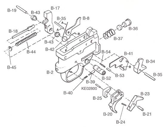
10/22 Trigger Work
Ruger 10/22 trigger disassembly.
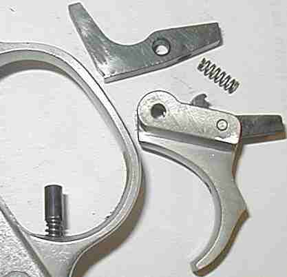
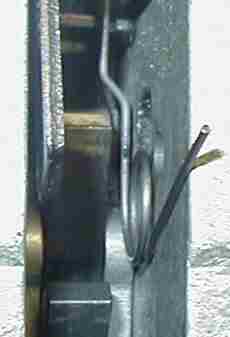
Left - The hammer strut and spring assembly (B18, B44, B45) is pulled out after un-cocking the hammer.
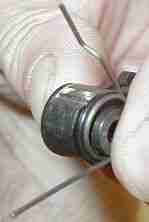
Center - The hammer pivot pin (B19) is pushed out.
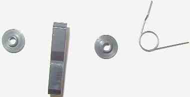
Right - The hammer (B17), hammer bushings 2 (B43), and bolt lock spring (B42) are removed.
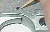
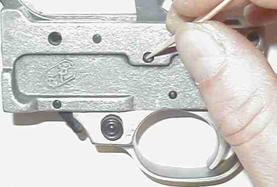
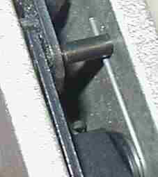
Left - The trigger pivot pin (B21) is pushed out.
Right - The trigger/disconnector/disconnector pivot pin assembly (B20, B25, KE-28), sear (B23) and sear spring (B24) are removed by pushing trigger through the top of trigger guard (B2).
-
Assemble 10/22 Trigger and Hammer
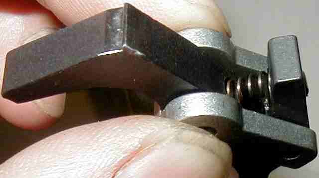
Left - The disconnector (B25) is pivoted so that the sear (B23) (sear spring hole facing up) lays below disconnector. The sear spring (B24) is then inserted in the spring holes on disconnector and sear.
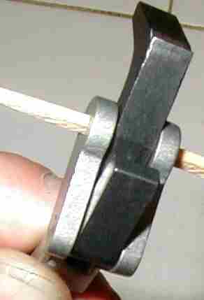
Right - To keep the assembly together while installing into trigger guard (B2), a round toothpick is inserted through trigger pivot pin hole and cut flush with trigger. The assembly is then put in place through the top of trigger guard. The trigger pivot pin (B21) is pushed through trigger guard and trigger with the temporary toothpick pin being pushed out the other side of trigger guard by the pivot pin.
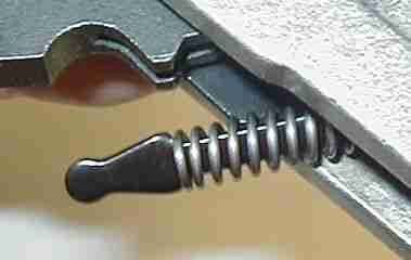
Left - The bottom arm of bolt lock spring (B42) (forward of bend in spring) lays in a small dimple on the top of bolt lock (B41).
Center and Right - The four hammer components (hammer, hammer bushings 2 , and bolt lock spring (B17, B43, B42)) are held in place and inserted into trigger guard (B2). The bolt lock spring is first placed on bolt lock (B41) as shown (above left). Then the assembly is slowly pulled backward until there is enough clearance to slip upper arm of spring under the magazine latch pivot & ejector pin (B35) as shown (above right). The hammer pivot pin (B19) is inserted through the trigger guard and hammer assembly.